
 Volkswagen
 BMW
BMW MINI
MINI Mercedes
 Ford
Ford Peugeot
 Citroën
 Opel
OpelThe whole valve train: from cam lobe to valve
Camshaft, lifter, pushrod, rocker arm and valve - how the valve train works as a system. Every component's role explained. A guide from Meksta.
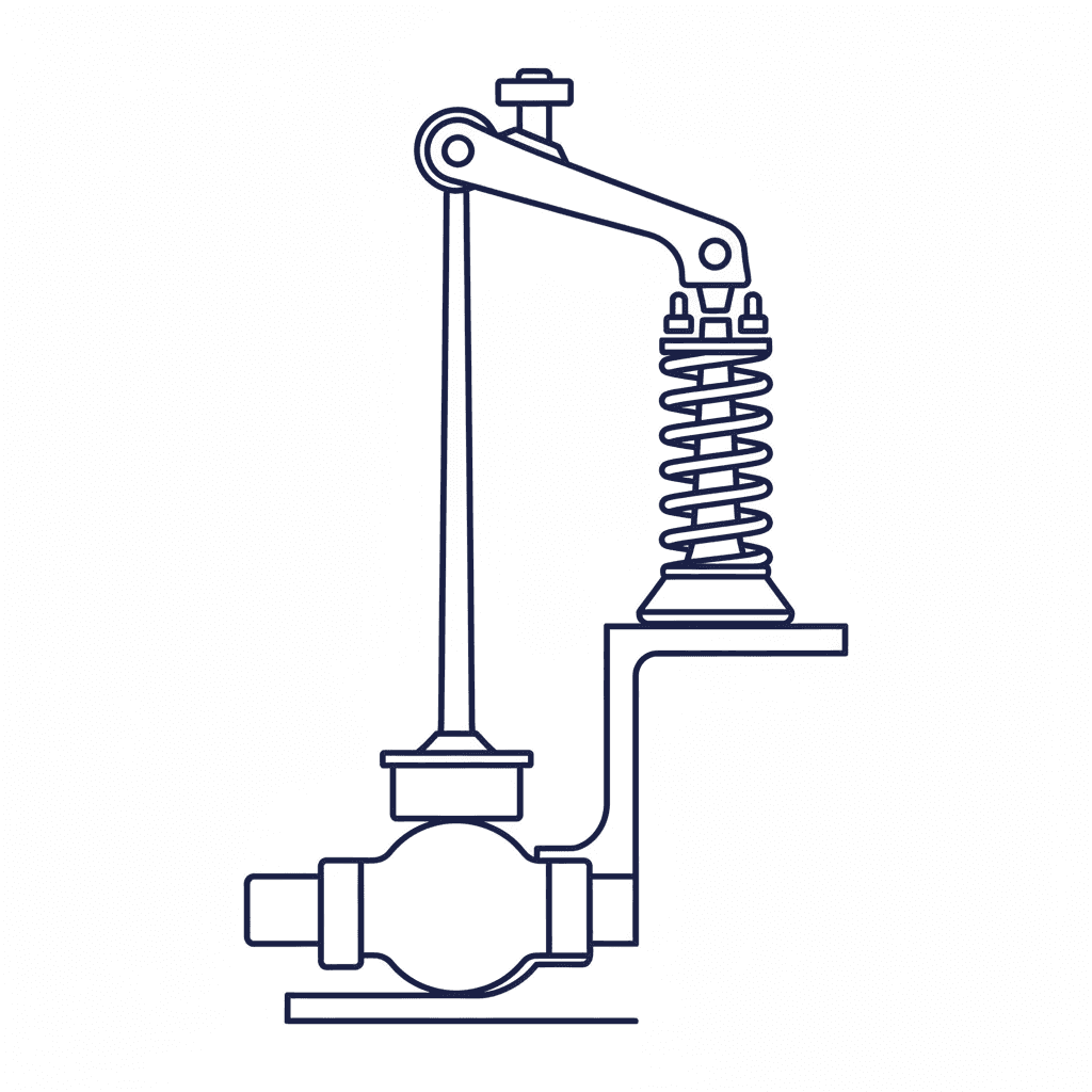
The camshaft designs the airflow, but it does not work alone. Between the cam lobe and the valve sits a chain of components that all have to work together: the lifter, the pushrod, the rocker arm and the valve spring. If a single link in the chain is weak, it does not matter how perfect the cam profile is.
The chain in an OHV valve train
In a classic OHV engine (overhead valve) with the camshaft in the block, the chain looks like this:
- Cam lobe - rotates and pushes the lifter upward. The profile's duration, lift and lobe separation determine the valve events.
- Lifter - follows the cam lobe. Flat tappet or roller, hydraulic or mechanical.
- Pushrod - transfers the motion from the lifter in the block up to the rocker arm on the head. A simple but critical component.
- Rocker arm - acts as a lever that inverts and amplifies the motion. The lifter pushes up, the rocker arm pushes the valve down.
- Valve - opens and closes the port opening in the head. Its linear motion is guided by the valve guide.
- Valve spring - closes the valve and keeps the whole chain in contact with the cam lobe.
OHC engines: a shorter chain
In an OHC engine (overhead cam) the camshaft sits in the head, directly above the valves. This eliminates pushrods and, in DOHC engines with bucket followers, rocker arms too. The cam lobe pushes directly on a bucket follower that sits on top of the valve stem.
CatCams, which designs cams for European OHC engines, has developed its own slipper followers that replace OEM roller finger followers. A shorter chain gives less elasticity, lower weight and a better ability to follow aggressive cam profiles at high rpm.
The pushrod: underrated but crucial
In an OHV engine, the pushrod is the weakest link in terms of stiffness. OnAllCylinders and modern engine builders emphasise that the trend has moved from standard 5/16" (about 8 mm) pushrods to thicker, tapered or elliptical designs in chrome moly steel.
Why does it matter? A pushrod that flexes under load absorbs some of the cam lobe's motion - the lifter is pushed up, but the rocker arm does not get the full motion. That effectively costs lift and changes the profile of the valve timing. The stronger the springs and the more aggressive the cam profile, the stiffer a pushrod is required. Column strength - the rod's resistance to buckling - is the relevant measure.
The rocker arm's leverage: rocker ratio
The rocker arm acts as a lever with different arm lengths on each side of the pivot point. The ratio between these lengths is called the rocker ratio, and it multiplies the cam lobe's lift.
Typical rocker ratios:
- Chevrolet small-block (older): 1.5:1 - a cam lobe with 7.6 mm lift gives 11.4 mm of valve lift
- GM LS-series: 1.7:1 - the same cam lobe gives 12.9 mm
- Ford Windsor: 1.6:1
Kent Cams specifies rocker ratios for all its engine applications (from 1.46:1 to 1.69:1 depending on the engine) and emphasises that it is the valve lift - not the cam lift - that determines the flow through the head.
A higher rocker ratio increases lift without changing the camshaft, but it also increases the acceleration in the valve train and places higher demands on springs and pushrods. It is not free power - it is redistributed load.
Valve float: when the chain breaks
Valve float occurs when the valve spring can no longer keep the lifter in contact with the cam lobe. The valve "floats" - it follows its own path instead of the lobe profile. COMP Cams and MooreGoodInk describe three related phenomena:
- Float - the spring cannot accelerate the valve back toward the seat fast enough. Most common at high rpm.
- Bounce - the valve bounces off the seat when closing. The spring closes the valve, but at too high a speed - the valve hits the seat and bounces back up again.
- Surge - the spring vibrates at its resonant frequency, losing control force. Beehive springs and dual springs dampen this.
All three mean the valve train loses control - and in an engine with a tight valve-to-piston margin, the result can be catastrophic.
Matching the components
The valve train is a system, not a collection of loose parts. COMP Cams emphasises that cam profile, lifter type, pushrod stiffness, rocker arm ratio and spring capacity all have to be sized as a whole:
- A more aggressive cam requires stiffer pushrods, stronger springs and possibly roller rockers
- A higher rocker ratio increases the load on the pushrod and spring
- A hydraulic lifter limits the rpm no matter how strong the springs are
- The wrong pushrod length changes the rocker arm's geometry and ruins the contact point on the valve stem
Summary
A camshaft delivers nothing without a valve train that can follow the profile all the way. Every component - from lifter to spring - has to be sized for the cam profile and the rpm you intend to run. Choosing the right cam starts with understanding the whole chain.
Contact Meksta - we make sure every part of the valve train works together.
About the author
Robert Wiklund has worked with engines for over 30 years, including for Mazda Rally Team Europe, Toyota Team Europe and GM's rally programme. He founded Meksta in 2023.
Read more about Meksta →Does your engine need reconditioning or tuning?
Contact us for expert advice, whether it is a crankshaft, a turbo upgrade or cylinder boring.